All SDGPS streams are prefixed with a configuration data structure that describes the information that is present in the stream. The raw, cooked, cooked2, and observables interface types share a common format that is described on this page. The solution interface has its own unique config format that is described on its page.
The only time that configs should need to be directly interacted with is when you're tweaking or creating a novel system model for a simulation.
Note: keys that are indented are nested within their parent, less-indented key. If a key is marked as required, it is only required if its parent is present.
| Key | Type | Unit | Required | Description |
|---|---|---|---|---|
| max_stream_jitter | Real | seconds | Yes | The maximum duration by which packets can be out of order in a stream, relative to their "stream times" |
| gnss_streams | Array of Objects | No | One object for each GNSS sample stream (each of which would typically correspond to one GNSS frontend IC capturing a given band from a given antenna) | |
i_bits | Integer | bits | Yes | Number of I (in-phase) bits of the raw GNSS bandband samples (typically 1, 2, or 3) |
q_bits | Integer | bits | Yes | Number of Q (quadrature) bits of the raw GNSS bandband samples (typically 1, 2, or 3) |
samples_per_packet | Integer | samples | Yes | Number of samples per GNSSSamplePacket (typically set so that sample packets are issued at about 20 Hz) |
sample_latency | Real | seconds | Yes | The approximate duration between the last sample of a GNSSSamplePacket being captured and the packet occurring within the stream |
sample_period | Real | seconds | Yes | The duration between samples |
spectrum_info | Object | No | (see SpectrumInfo ) | |
substreams | Array of Objects | No | (see Substream ) | |
| imu | Object | No | A description of the IMU, if an IMU is present (Note: the IMU must be present at the body-frame origin and aligned with the body axes) | |
covariance | 6x6 matrix | [m/s^2 rad/s] | Yes | The covariance of the noise of a single IMU measurement |
sample_latency | Real | seconds | Yes | The duration between the "measurement time" (the time at which the measurement occurs) and the "stream time" (the time at which the measurement should be issued in the stream) |
sample_period | Real | seconds | Yes | The duration between samples |
| baro_streams | Array of Objects | No | One object for each barometric pressure sensor | |
position | 3-vector | meters | Yes | The position in the body frame where barometric pressure is measured |
sample_latency | Real | seconds | Yes | The duration between the "measurement time" (the time at which the measurement occurs) and the "stream time" (the time at which the measurement should be issued in the stream) |
sample_period | Real | seconds | Yes | The duration between samples |
variance | Real | pascals^2 | Yes | The variance of a single barometric pressure measurement |
| mag_streams | Array of Objects | No | One object for each magnetometer sensor | |
covariance | 3x3 matrix | tesla^2 | Yes | The covariance of a single measurement |
orientation | quaternion | Yes | The orientation of the magnetometer axes in the body frame, represented as a quaternion that rotates magnetometer-frame vectors into body-frame vectors | |
sample_latency | Real | seconds | Yes | The duration between the "measurement time" (the time at which the measurement occurs) and the "stream time" (the time at which the measurement should be issued in the stream) |
sample_period | Real | seconds | Yes | The duration between samples |
| tick_stream | Object | No | Present if TickPackets exist within the stream; necessary if there are no high-rate sensors (e.g. IMU, mag, baro) to convey time | |
sample_latency | Real | seconds | Yes | The duration between the "measurement time" (the time at which the measurement occurs) and the "stream time" (the time at which the measurement should be issued in the stream) |
sample_period | Real | seconds | Yes | The duration between samples |
The optional spectrum_info key in a gnss_stream Object describes GNSS-agnostic information about the downconverted band. It has the following information:
| Key | Type | Unit | Required | Description |
|---|---|---|---|---|
| lo_frequency | Real | Hz | Yes | RF frequency that 0 Hz in downconverted band corresponds to (= LO frequency) |
| band_start | Real | Hz | Yes | lowest RF frequency captured (= low edge of SAW passband) |
| band_end | Real | Hz | Yes | highest RF frequency captured (= high edge of SAW passband) |
The Objects inside the optional substreams Array in a gnss_stream Object each describe one GNSS signal that is present in the GNSS stream. They have the following information:
| Key | Type | Unit | Required | Description |
|---|---|---|---|---|
| axis | unit 3-vector | No | Direction of antenna axis (boresight) in body frame | |
| position | 3-vector | meters | No | Position of antenna phase center in body frame |
| frequency | Real | Hz | Yes | Frequency of this GNSS signal in the downconverted band (e.g. 0 Hz for zero-IF downconversion) |
| system | String | Yes | GNSS signal. Current options: GPS_L1, GPS_L2C, GLO_L1, GLO_L2, GAL_E1B | |
| forward | unit 3-vector | No | Direction of antenna frame x-axis in body frame | |
| correlator_spacing | Real | samples | In cooked/cooked2 streams | Spacing between correlator taps |
| correlator_count | Integer | In cooked/cooked2 streams | Number of correlator taps | |
| correlation_latency | Real | seconds | In cooked/cooked2 streams | The duration between the "measurement time" (the time at which the measurement occurs) and the "stream time" (the time at which the measurement should be issued in the stream) |
| correlator_obeys_configuration_exactly | Boolean | In cooked/cooked2 streams | true if and only if the correlator will immediately and exactly (no rounding/etc.) obey DesiredCorrelatorConfigurations | |
| observation_latency | Real | seconds | In observables streams | The duration between the "measurement time" (the time at which the measurement occurs) and the "stream time" (the time at which the measurement should be issued in the stream) |
The following is a valid config for a fictional platform with two GPS_L1 antennas spaced 1 meter apart along the body X axis and pointing along the body +Z axis:
After saving the above config to a file named configs/dual, we can run the following commands to perform various simulations:
This shows the IMU output while the vehicle is being rotated around its +X axis.
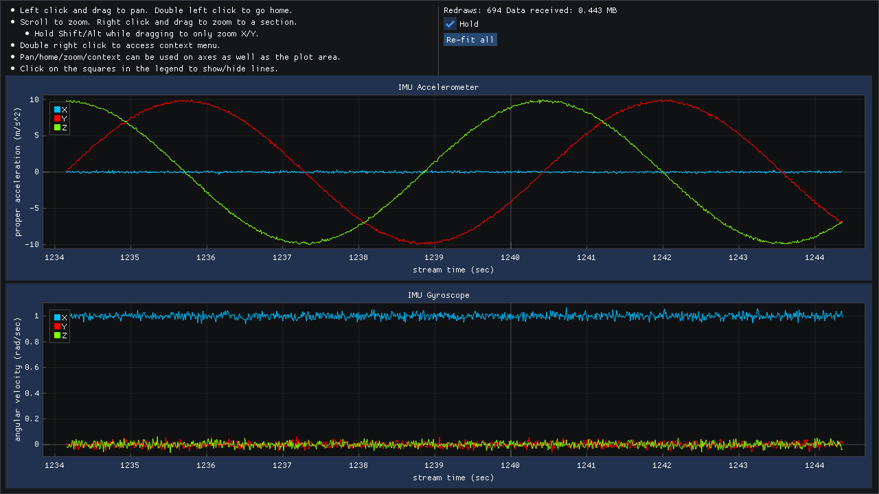 |
| Simulation 1 |
This shows the observables from both GNSS antennas while the vehicle is being rotated about its +Z axis.
 |
| Simulation 2 |
The following was output by running sdgps print-config ugi2:.
From this, we can see that the Infix-2 has a barometer, magnetometer, and IMU. In addition, it has a single 2-bit GNSS frontend that can receive the GPS_L1 signal.