NOTE: This page is out-of-date. Please refer to Getting started with the Infix-2.
Congratulations on your purchase of an Infix-1!
|
 |
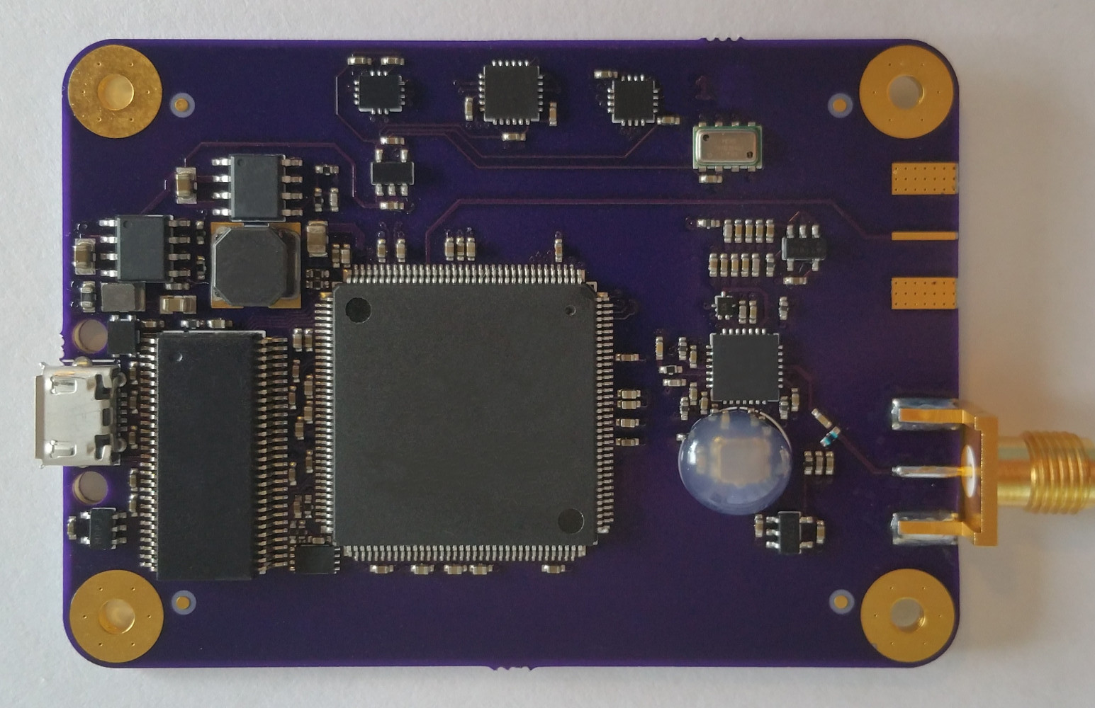
| Infix-1 PCB |
Included in the kit are the following:
- Sylphase Infix-1 PCB
- Low-PCV GPS Antenna - datasheet
- 6 ft micro USB cable
- 3D printed mounting bracket that also acts as a strain relief
- Zip ties for strain relief
Mechanical considerations
|
 |
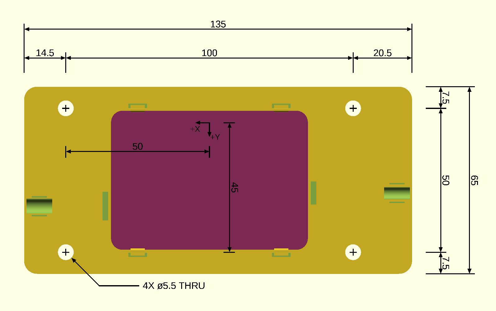
| Mechanical drawing of the 3D-printed mounting bracket supplied with the Infix-1 (units: mm) |
The Infix-1 is mounted on a provided carrier bracket that adapts its M2.5 hole pattern to a larger M5 hole pattern. The bracket also provides strain relief for the USB and antenna cables.
When you first receive your Infix-1, connect a micro-USB cable and the antenna to the Infix-1 PCB, then use the provided zip ties to fasten them to the strain relief standoffs.
The Infix-1 and antenna need to both be mounted rigidly to the vehicle whose position is to be measured. The antenna needs an open view of the sky, and so should be mounted on the highest point on the vehicle. The Infix-1 is sensitive to changing magnetic fields, and so should be mounted at least 1 meter from any metal that can move (e.g. a car door) or anything that generates a changing magnetic field (e.g. an electric motor). The antenna comes with an embedded magnet for mounting, so the antenna should not be located close to the Infix-1.
The Infix-1 has an axes reference on the top, which defines its local coordinate system. We recommend mounting the Infix-1 so that the X axis points in the "forward" direction of the vehicle, the Y axis points in the "left" direction of the vehicle, and the Z axis points in the "up" direction of the vehicle.
The position of the center of the antenna in the local coordinate system of the Infix-1 must be known and supplied to the SDGPS software. Measure it with error not exceeding 5 centimeters.
Install SDGPS
Install SDGPS
Setup complete
At this point, you should have the Infix-1 hardware connected and fastened and the SDGPS software installed.
A simple test
Try running the following command to make sure that everything is working:
sdgps sylphase-usbgpsimu2 ! tracker ! decoder
You should get output similar to the following:
sylphase-usbgpsimu2: Programming...
sylphase-usbgpsimu2: ...done. Waiting for device to reconnect...
sylphase-usbgpsimu2: ...done!
sylphase-usbgpsimu2: Opened device with ID 76e6
sylphase-usbgpsimu2: DONE=0, INIT_B=1
sylphase-usbgpsimu2: Resetting...
sylphase-usbgpsimu2: DONE=0, INIT_B=0
sylphase-usbgpsimu2: DONE=0, INIT_B=0
sylphase-usbgpsimu2: DONE=0, INIT_B=0
sylphase-usbgpsimu2: DONE=0, INIT_B=0
sylphase-usbgpsimu2: DONE=0, INIT_B=0
sylphase-usbgpsimu2: DONE=0, INIT_B=0
sylphase-usbgpsimu2: DONE=0, INIT_B=0
sylphase-usbgpsimu2: DONE=0, INIT_B=0
sylphase-usbgpsimu2: DONE=0, INIT_B=1
sylphase-usbgpsimu2: Starting load...
sylphase-usbgpsimu2: ...load finished.
sylphase-usbgpsimu2: DONE=1, INIT_B=1
sylphase-usbgpsimu2: Success!
sylphase-usbgpsimu2: ACQUIRED GPS_L1 Signal# 20 [Doppler: 3439.83] [C/N_0: 36.565]
sylphase-usbgpsimu2: ACQUIRED GPS_L1 Signal# 24 [Doppler: 4539.83] [C/N_0: 32.8479]
sylphase-usbgpsimu2: ACQUIRED GPS_L1 Signal# 13 [Doppler: -355.172] [C/N_0: 33.8424]
sylphase-usbgpsimu2: ACQUIRED GPS_L1 Signal# 21 [Doppler: 3724.83] [C/N_0: 34.9116]
sylphase-usbgpsimu2: ACQUIRED GPS_L1 Signal# 29 [Doppler: -210.172] [C/N_0: 36.029]
sylphase-usbgpsimu2: ACQUIRED GPS_L1 Signal# 10 [Doppler: 4049.83] [C/N_0: 31.9935]
sylphase-usbgpsimu2: ACQUIRED GPS_L1 Signal# 5 [Doppler: -875.172] [C/N_0: 34.2943]
sylphase-usbgpsimu2: ACQUIRED GPS_L1 Signal# 15 [Doppler: 1194.83] [C/N_0: 33.2932]
tracker: GPS_L1 Signal#: 29 alignment check failed (reason: z test failed)
decoder: SV#: 20 PREAMBLED!
decoder: SV#: 13 PREAMBLED!
decoder: SV#: 24 PREAMBLED!
decoder: SV#: 21 PREAMBLED!
decoder: SV#: 10 PREAMBLED!
decoder: SV#: 15 PREAMBLED!
decoder: SV#: 5 PREAMBLED!
decoder: SV#: 29 PREAMBLED!
decoder: 70 seconds elapsed, only confirmed ephemerides will be used from this time on
[GPS_L1 8/8/32] [GPS_L1 7/8/32]
If you output appears similar to this, you are successfully tracking GPS satellites. The status bar at the bottom displays the number of satellites being successfully tracked (8) and decoded (7).
A simple test (no antenna)
If you do not yet have an antenna but have your Infix-1, you can still use simulated data to operate:
With your Infix-1 plugged in, run the following command:
sdgps generate-simple-trajectory --angular-velocity-enu '[0,0,1]' ! simulate-raw ugi2: ! sylphase-usbgpsimu2-offline ! tracker ! decoder
This will produce an output similar to the following:
sylphase-usbgpsimu2-offline: Programming...
sylphase-usbgpsimu2-offline: ...done. Waiting for device to reconnect...
sylphase-usbgpsimu2-offline: ...done!
sylphase-usbgpsimu2-offline: Opened device with ID 73b9
sylphase-usbgpsimu2-offline: DONE=0, INIT_B=1
sylphase-usbgpsimu2-offline: Resetting...
sylphase-usbgpsimu2-offline: DONE=0, INIT_B=0
sylphase-usbgpsimu2-offline: DONE=0, INIT_B=0
sylphase-usbgpsimu2-offline: DONE=0, INIT_B=0
sylphase-usbgpsimu2-offline: DONE=0, INIT_B=1
sylphase-usbgpsimu2-offline: Starting load...
sylphase-usbgpsimu2-offline: ...load finished.
sylphase-usbgpsimu2-offline: DONE=1, INIT_B=1
sylphase-usbgpsimu2-offline: Success!
simulate-raw: GPS_L1 SV 12 came into view
simulate-raw: GPS_L1 SV 16 came into view
simulate-raw: GPS_L1 SV 15 came into view
simulate-raw: GPS_L1 SV 21 came into view
simulate-raw: GPS_L1 SV 8 came into view
simulate-raw: GPS_L1 SV 22 came into view
simulate-raw: GPS_L1 SV 25 came into view
simulate-raw: GPS_L1 SV 1 came into view
simulate-raw: GPS_L1 SV 26 came into view
simulate-raw: GPS_L1 SV 29 came into view
simulate-raw: GPS_L1 SV 4 came into view
simulate-raw: GPS_L1 SV 5 came into view
sylphase-usbgpsimu2-offline: ACQUIRED GPS_L1 Signal# 26 [Doppler: -3615.17] [C/N_0: 31.6224]
sylphase-usbgpsimu2-offline: ACQUIRED GPS_L1 Signal# 4 [Doppler: 2379.83] [C/N_0: 32.3237]
sylphase-usbgpsimu2-offline: ACQUIRED GPS_L1 Signal# 21 [Doppler: 424.828] [C/N_0: 31.7132]
sylphase-usbgpsimu2-offline: ACQUIRED GPS_L1 Signal# 22 [Doppler: -2465.17] [C/N_0: 35.014]
sylphase-usbgpsimu2-offline: ACQUIRED GPS_L1 Signal# 25 [Doppler: 1659.83] [C/N_0: 38.3606]
sylphase-usbgpsimu2-offline: ACQUIRED GPS_L1 Signal# 16 [Doppler: 84.8276] [C/N_0: 32.2037]
sylphase-usbgpsimu2-offline: ACQUIRED GPS_L1 Signal# 12 [Doppler: 84.8276] [C/N_0: 37.186]
sylphase-usbgpsimu2-offline: ACQUIRED GPS_L1 Signal# 1 [Doppler: -945.172] [C/N_0: 36.172]
sylphase-usbgpsimu2-offline: ACQUIRED GPS_L1 Signal# 8 [Doppler: 1194.83] [C/N_0: 34.8892]
sylphase-usbgpsimu2-offline: ACQUIRED GPS_L1 Signal# 29 [Doppler: 1194.83] [C/N_0: 34.4229]
sylphase-usbgpsimu2-offline: ACQUIRED GPS_L1 Signal# 5 [Doppler: -2815.17] [C/N_0: 35.2329]
decoder: SV#: 25 PREAMBLED!
decoder: SV#: 26 PREAMBLED!
decoder: SV#: 22 PREAMBLED!
decoder: SV#: 4 PREAMBLED!
decoder: SV#: 21 PREAMBLED!
tracker: GPS_L1 Signal#: 1 alignment check failed (reason: z test failed)
sylphase-usbgpsimu2-offline: ACQUIRED GPS_L1 Signal# 15 [Doppler: 3269.83] [C/N_0: 36.5048]
tracker: GPS_L1 Signal#: 8 alignment check failed (reason: z test failed)
decoder: SV#: 12 PREAMBLED!
decoder: SV#: 16 PREAMBLED!
tracker: GPS_L1 Signal#: 5 alignment check failed (reason: z test failed)
decoder: SV#: 29 PREAMBLED!
decoder: SV#: 1 PREAMBLED!
decoder: SV#: 15 PREAMBLED!
tracker: GPS_L1 Signal#: 5 alignment check failed (reason: z test failed)
decoder: SV#: 8 PREAMBLED!
decoder: SV#: 5 PREAMBLED!
decoder: 70 seconds elapsed, only confirmed ephemerides will be used from this time on
If your output appears similar to this, you are successfully simulating raw signals and tracking GPS satellites.
Tutorial
Try following the SDGPS tutorial to familiarize yourself with SDGPS. Email suppo.nosp@m.rt@s.nosp@m.ylpha.nosp@m.se.c.nosp@m.om if you have any trouble or questions.
Make sure you read the inertial-kf2 page to learn the initialization procedure required at startup.
Normal operation
Normal operation of the Infix-1, integrated into your system, will have SDGPS being run in a GNU screen session at startup. See doc/Run_on_system_startup.md.
The simplest possible operation is one SDGPS instance running with a command similar to:
sdgps sylphase-usbgpsimu2 --antenna-position '[1,2,3]' ! tracker ! decoder ! inertial-kf2 --output-rate 100 ! listen-solution-tcp 1234
Then, your custom software would connect to localhost on port 1234 and parse the solution stream that is produced. The solution stream format is newline-delimited JSON. You can look directly it at while running the above command by using netcat:
You might want to run inertial-kf2 in a different SDGPS process (as recommended in doc/Run_on_system_startup.md) e.g. so that the Kalman filter can easily be restarted without having to reacquire satellites.
A representative snippet of output is included here to get an idea of how the solution stream is formatted and what data it contains:
{
"max_sample_latency_relative_to_observables": 0.134500001,
"sample_offset": 5e-4,
"sample_rate": 100,
"type": "solution_v6"
}
{
"X_accel_bias": [5.772898684984456e-4, -0.043412037050573, -0.0032404362127670125],
"X_accel_bias_covariance": [[1.640831592508146e-5, 2.5207041817004714e-6, 2.1951539711241774e-7], [2.5207041817004714e-6, 3.2167963599526324e-4, -1.6424473202106305e-6], [2.1951539711241774e-7, -1.6424473202106305e-6, 2.465447413314541e-5]],
"X_acceleration_body": [0.0936846766175221, -0.0718409838377154, 0.12202423807822993],
"X_air_pressure": 101317.5981110497,
"X_air_pressure_variance": 0.04212188311244832,
"X_angular_velocity_body_covariance": [[4.007557855982573e-4, 1.3972828701826157e-8, 6.540217878443092e-8], [1.3972828701826157e-8, 4.037095119991735e-4, -3.7694720388294095e-8], [6.540217878443092e-8, -3.7694720388294095e-8, 4.0058842266924694e-4]],
"X_clock_error": 4.031242006874436e-11,
"X_gravity_model_error_ecef": [2.543129661478755e-4, -0.0013857594523795412, 9.307437093958046e-4],
"X_gravity_model_error_ecef_covariance": [[9.489769009058858e-5, 8.546542550302693e-6, -3.661970389569136e-6], [8.546542550302693e-6, 3.479426303105889e-5, 3.182199769803948e-5], [-3.661970389569136e-6, 3.182199769803948e-5, 7.152570530007124e-5]],
"X_gyro_bias": [4.4239722911775144e-4, -0.0046690525879912095, 2.696703085362362e-4],
"X_gyro_bias_covariance": [[7.557855982573067e-7, 1.3972828701826157e-8, 6.540217878443092e-8], [1.3972828701826157e-8, 3.7095119991734874e-6, -3.7694720388294095e-8], [6.540217878443092e-8, -3.7694720388294095e-8, 5.884226692469212e-7]],
"X_mag_bias": [1.7698127308614004e-8, 2.966420634807741e-7, -1.3021287043047663e-7],
"X_mag_bias_covariance": [[2.1186430423647773e-15, 1.3886285808665792e-15, 4.044073585119515e-16], [1.3886285808665792e-15, 1.0705211651564647e-14, 8.374931650581545e-16], [4.044073585119515e-16, 8.374931650581545e-16, 5.956670184509909e-15]],
"X_mag_scale": [[1.0001249109108208, 6.25564437561232e-4, -6.144312714488263e-4], [6.25564437561232e-4, 1.0008563207503427, 0.0024136044334809505], [-6.144312714488263e-4, 0.0024136044334809505, 0.9961461837920328]],
"X_magnetic_model_error_ecef": [-7.556758433646984e-9, 1.7565956285557308e-8, -7.3455034255377395e-9],
"X_magnetic_model_error_ecef_covariance": [[2.6740870940514687e-14, 1.2845938830565427e-15, 2.101682532454647e-15], [1.2845938830565427e-15, 2.0267169643433703e-14, 3.8096627054311583e-16], [2.101682532454647e-15, 3.8096627054311583e-16, 4.02249209709181e-15]],
"X_position_ecef_covariance": [[0.01018626936217126, 0.0035914905107538755, -0.0016263266022773922], [0.0035914905107538755, 0.07102907971729046, -0.020854922511796124], [-0.0016263266022773922, -0.020854922511796124, 0.017135297799981946]],
"X_position_relative_position_orientation_ecef_covariance": [[0.01018626936217126, 0.0035914905107538755, -0.0016263266022773922, 2.6512945765512712e-5, 1.1497028442999543e-5, -7.1307860219601444e-6, -3.613942856456033e-8, 1.5071830305521702e-7, 4.6022842152276894e-8], [0.0035914905107538755, 0.07102907971729046, -0.020854922511796124, -3.147333617828279e-5, 1.1463445688173283e-4, -2.4580373905537454e-5, -1.94150450111438e-7, 1.8171506798268283e-7, -7.570595469787245e-9], [-0.0016263266022773922, -0.020854922511796124, 0.017135297799981946, 8.545507451525153e-6, -2.668927646813007e-5, 3.5773766364883416e-5, -4.012528865170478e-8, -6.828655580240779e-8, -2.5279917604762563e-9], [2.6512945765512712e-5, -3.147333617828279e-5, 8.545507451525153e-6, 5.7645753897806515e-5, 2.5691085929058094e-5, -1.169089350299197e-5, -3.128857628173413e-8, 1.1388985012537871e-8, 5.036575125218237e-8], [1.1497028442999543e-5, 1.1463445688173283e-4, -2.668927646813007e-5, 2.5691085929058094e-5, 3.944802986943812e-4, -1.184015939156763e-4, -8.702896413279459e-8, 9.376677140541734e-8, 9.358793032539319e-8], [-7.1307860219601444e-6, -2.4580373905537454e-5, 3.5773766364883416e-5, -1.169089350299197e-5, -1.184015939156763e-4, 9.749469261048718e-5, 2.1453174279221005e-9, -1.1914451647470879e-7, -3.101432231676783e-9], [-3.613942856456033e-8, -1.94150450111438e-7, -4.012528865170478e-8, -3.128857628173413e-8, -8.702896413279459e-8, 2.1453174279221005e-9, 5.486630597770572e-6, -5.636735918473298e-6, 2.166238549848746e-6], [1.5071830305521702e-7, 1.8171506798268283e-7, -6.828655580240779e-8, 1.1388985012537871e-8, 9.376677140541734e-8, -1.1914451647470879e-7, -5.636735918473298e-6, 4.1183005746762104e-5, -2.0918277449862864e-5], [4.6022842152276894e-8, -7.570595469787245e-9, -2.5279917604762563e-9, 5.036575125218237e-8, 9.358793032539319e-8, -3.101432231676783e-9, 2.166238549848746e-6, -2.0918277449862864e-5, 1.3088396494538796e-5]],
"X_relative_position_orientation_enu_covariance": [[7.045457311724489e-5, 1.0501990712555233e-5, -7.382981176521527e-5, -3.9069526468400425e-8, 6.873104488193126e-8, 5.423412861179579e-9], [1.0501990712555226e-5, 6.74919655091309e-5, -6.307660531198102e-5, -4.618041953125698e-8, 8.607651901465292e-9, 6.545475090999871e-8], [-7.382981176521527e-5, -6.307660531198104e-5, 4.116742065762991e-4, 5.3254827274217226e-8, -1.3893191209763533e-7, 8.983863745894156e-8], [-3.906952646840041e-8, -4.618041953125697e-8, 5.3254827274217226e-8, 4.631205920688946e-6, -9.139134770735842e-7, 2.97832509953695e-7], [6.873104488193126e-8, 8.60765190146529e-9, -1.389319120976353e-7, -9.13913477073584e-7, 2.0991560857853495e-6, -1.7164415738047755e-6], [5.4234128611795835e-9, 6.54547509099987e-8, 8.983863745894156e-8, 2.9783250995369516e-7, -1.7164415738047767e-6, 5.302767083259719e-5]],
"X_svs_used": {
"GPS_L1": {
"12": {
"ionospheric_delay_estimate": {
"mean": 0,
"stddev": 5.024835299005121
}
},
"15": {
"ionospheric_delay_estimate": {
"mean": 0,
"stddev": 5.024766067473533
}
},
"16": {
"ionospheric_delay_estimate": {
"mean": 0,
"stddev": 5.024855097000396
}
},
"19": {
"ionospheric_delay_estimate": {
"mean": 0,
"stddev": 5.024810562484445
}
},
"2": {
"ionospheric_delay_estimate": {
"mean": 0,
"stddev": 5.024780894754301
}
},
"22": {
"ionospheric_delay_estimate": {
"mean": 0,
"stddev": 5.024855097000396
}
},
"23": {
"ionospheric_delay_estimate": {
"mean": 0,
"stddev": 5.024775951839647
}
},
"26": {
"ionospheric_delay_estimate": {
"mean": 0,
"stddev": 5.024800671290177
}
},
"29": {
"ionospheric_delay_estimate": {
"mean": 0,
"stddev": 5.024771009412724
}
},
"30": {
"ionospheric_delay_estimate": {
"mean": 0,
"stddev": 5.024775951839647
}
}
}
},
"X_velocity_body_covariance": [[1.8494758504647274e-5, -5.353876426165563e-7, -1.8144175406587396e-7], [-5.353876426165563e-7, 2.024933000943323e-5, -7.4086375449695236e-6], [-1.8144175406587396e-7, -7.4086375449695236e-6, 3.7109935451964805e-5]],
"X_velocity_ecef_covariance": [[1.860132494641837e-5, 2.4913514156683683e-6, -1.2182258161818329e-6], [2.4913514156683683e-6, 3.876344396935478e-5, -4.132416989834382e-6], [-1.2182258161818329e-6, -4.132416989834382e-6, 1.8483443058597666e-5]],
"X_velocity_enu_covariance": [[1.9620447936355317e-5, 9.79983928062429e-7, -5.2773441391758995e-6], [9.799839280624294e-7, 1.9816027634132888e-5, -6.2735222213666105e-6], [-5.2773441391759e-6, -6.273522221366613e-6, 3.641173640388261e-5]],
"angular_velocity_body": [0.18192399265174128, 1.2318259960803433, 0.9804527251738685],
"index": 0,
"orientation_ecef": {
"w": 0.8667823824704268,
"x": 0.48692261682402727,
"y": 0.026082740752655376,
"z": -0.1044718014536073
},
"orientation_enu": {
"w": 0.9866807098048901,
"x": -0.009666317876782005,
"y": -0.08722533374497438,
"z": -0.1369652523478169
},
"position_ecef": [740883.0293625188, -5497747.156404508, 3136908.0048778676],
"relative_position_ecef": [3.6252196186996793e-4, -0.0011594383977353573, -6.00746635027103e-4],
"relative_position_enu": [2.0442674437891293e-4, -0.0011145008186418694, 7.434471883777703e-4],
"running": true,
"time": "1298764834.728512375013176137",
"velocity_body": [-6.532209566222929e-4, 0.002956152279015257, -0.001276668811005813],
"velocity_ecef": [4.456086945196044e-5, 0.002676174221568583, 0.0019056555388154792],
"velocity_enu": [4.015753171083585e-4, 0.0029652834422250894, -0.0013569261364745262]
}
ROS bridge
SDGPS includes a rospy bridge script in scripts/solution_ros_bridge. It takes parameters:
_host: the IP/hostname to connect to SDGPS (default: localhost)_port: the TCP port to connect to SDGPS_child_frame_id: the TF frame for the INS (e.g. /ins)_decimation: only pass through one of every N solutions; useful if ROS nodes are being overwhelmed by the update rate (default: 1)_force_z_to_zero: always output a Z coordinate of 0; useful for vehicles that will not move vertically (e.g. land or water vehicles) (default: False)
It publishes:
Run it with a command like:
scripts/solution_ros_bridge _port:=1234 _child_frame_id:=/ins
and then look at the output with:

